Just Released! EARTHQUAKE RESISTANT BUILDING from reinforced concrete - Volume C' Buy Now
Special Offer! Get the PDF books of Volume A and B at a discounted price! Buy Now
project < Β_422-2>
The structure of this example derives from 1st example by removing the two middle beams. The aspect ratio for both slabs is ε=Ly/Lx=12.0/4.0=3.0> 2.0, therefore they can be treated and analysed as two continuous one-way slabs.
For 1.00 m wide slab strip:
Self-weight: go=0.15m×1.00m×25.00 kN/m3= 3.75 kN/m, Covering load: ge=1.00 kN/m (given),
Total dead load: g=4.75 kN/m, Live load: q=5.00 kN/m (given).
Thus, the total load is p=γg×g+γq×q=1.35×4.75+1.50×5.00=13.9 kN/m. The bending moment at the support is calculated using table b3, line 1.
M1=-p×L2/8=-13.9×4.02/8=-27.8 kNm,
V01=p×L/2+M1/L=13.9×4.0/2-27.8/4.0= =20.8 kN
V10= p×L/2-M1/L=13.9×4.0/2+27.8/4.0= =34.8 kN
maxM01=V012/(2×p)=20.82/(2×13.9)= =15.6 kNm
According to §4.5.2, from expression (3) →
C1=(-13.9×4.03/24+20.8×4.02/6)m2= =18.4 kN×m2
Expression (4) →
(13.9/6)z3-(20.8/2)z2-0+18.4=0 →
2.317z3-10.4z2+18.4=0 →zmax=1.68 m
(2) → y(z)=1/9.225×[(13.9/24)×1.684-(20.8/6)×1.683+0×1.682+18.4×1,68)] → y(1.68)=2.07 mm
Before analysing, set these parameters, as in 1st example: Tab Meshing: “Overall size” = 0.10 m, “Perimeter size” = 0.05 m, Tab Modules: “SLABS” = ON, Tab Loads: “Adverse Slabs” = ΟΝ.
For most of the region towards direction y, the slab is curved only along direction x.
to the respective values of the one-way slabs, calculated previously.
Also, shears [Vy] extend in an area near the supports with maximum value of 15.0 kN.
In the largest part, it matches the corresponding distribution of one-way slabs.
Shear forces [Vy] extended only to the regions of end supports.
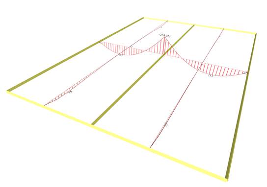
Notice that in the middle cross-section, the moments [Mx] 15.5 and -27.4 kNm, are equal to the values of the one-way slabs calculated previously.
On the other hand, moments [My] do exist, 3.6 kNm, but they are insignificant.
Along most of the region, it resembles the corresponding distribution of one-way slabs.
Bending moments [My] are small and extended only in the regions of end supports.
Notice that in the middle cross-section, the deflection is 2.10 mm, that is equal to the respective deflection of the one-way slabs calculated previously.