Menu

Frame column stiffness


Materials
To be continued >
Introduction

Frame column stiffness

Frame column stiffness in direction j (j=x, y):

Frames could comprise either columns only, called “frame systems” or columns and walls called “dual systems”. These two types of frame systems will be considered in the following paragraphs.

One-storey frame structural systems

The structural frame model without rigid bodies but fully stiffened

In project <B_5151a> of the related software, the cross-section of all columns is 400/400 and their height 3.0 m. The cross-section of the flanged beams is 300/500/1300/150 and their span 6.0 m. The seismic horizontal force is equal to 50 kN.


Analysis results of project < B_5151a > with full beam and column stiffness
(graphical representation in the related software)

Elastic line, δ=0.695 mm

Shear force diagrams

Bending moment diagrams

Example of one-storey structural systems with foundation

The structural frame model fully stiffened, project <B_5151b>

Project <B_5151b> derives from project <B_5151a> by adding foundation beams with cross-section 300/800/1500/400 at level

-0.80 m

.


Analysis results of project with actual beam and column stiffness
(graphical representation in the related software)

Elastic line, δ=1.480 mm

Shear force diagrams

Bending moment diagrams

One-storey dual structural systems

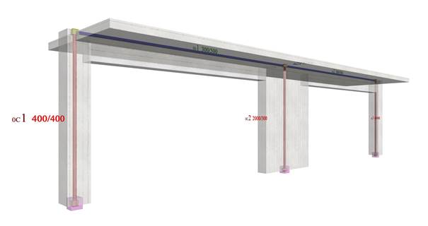
One-storey dual type structure comprising two columns and a wall (project <B_5152a>)

In project <B_5152a> of the related software, the structure comprises two end columns and a wall in the middle with cross-sections 400/400 and 2000/300 respectively. Their height is 3.0 m. The cross-section of the flanged beams is 300/500/1300/150 and their span is 6.0 m. The horizontal seismic force is50 kN.


Analysis results of project <B_5152a> with actual beam and column stiffnesses
(graphical representation in the related software)

Elastic line, δ=0.059 mm

Shear force diagrams

Bending moment diagram

Example of a One-storey dual structural systems with foundation

The structural frame with the actual stiffness in project <B_5152b>

Project <B_5152b> derives from project <B_5152a> by adding at level -0.80 m flanged foundation beams with cross-section 300/800/1500/400.


Analysis results of project with actual beam and column stiffness
(graphical representation in the related software)

Elastic line, δ=0.382 mm

Shear force diagram

Bending moment diagram