en-USel-GRes-ES
Menu

3rd example


Materials
To be continued >
Introduction

3rd example

project <Β_422-3>

The structure of this example derives from the 1st example by removing beams b1, b2 and appending a cantilever at the side of beams b5 and b6.


The actual stucture in 3D

The thickness of all slabs is 190 mm satisfying the slenderness. S1, S2 are three-edge-supported slabs. Slab s5 is cantilever, carrying additional concentrated linear dead load G=1.0 kN/m on its free edges. The cantilever is fixed along the small side of the two-way slabs s3 and s4. To per-form analysis set these parameters: Tab “Meshing”: “Overall size” = 0.10 m, “Perimeter size” = 0.05 m, Tab “Modules”: “SLABS” = ON, Tab “Loads”: “Adverse Slabs” = ΟΝ.

The deformation of slabs in 3D

Two, statically interesting, regions will be examined separately. The first comprises the two three-edge-supported slabs. The second comprises the cantilever and the two two-way slabs. The appropriate slabs are selected by pressing “Single” in the section “selection”.

Shear forces from ‘Slab Results’

The highest shears Vx varying from 23.1 to 38.8 kN, are developed at the free edge. Vx are somewhat smaller at the middle cross-section, varying from 21.1 to 36.4 kN. Shears Vy vary from 0.0 to 31.3 kN.


The 3D distribution of shear forces [Vx]

The above values refer to the section of the ‘Slab Results’ calculated from the integration of the stress resultants in distribution width 1.0 m. The respective values of the ‘FEM Results’ Vx vary from 27.7 to 40.8 kN at the free edges and from 21.1 to 36.6 kN at the middle cross-section. Shears Vy from 0.0 έως 31.9 kN. These differences are considerable only in the region of the free edges where there is a “crumple” as shown in the following 3D distribution of shears and especially in the side view of the 3D.


The 3D distribution of shear forces [Vy]

Shear forces [Vy] extend only in the regions of the middle supports.


Bending moments from ‘Slab Results’

One notices that the higher moments Mx, 16.9 kNm at the opening and -30.0 kNm at the support, are developed at the free edge. The values of Mx are lower at the middle cross-section, (13.8 kNm at the opening and -26.0 kNm at the support). Moments Μy vary from 0.0 to -17.4 kN

The 3D distribution of bending moments [Mx]

The above values refer to the ‘Slab Results’ section calculated from the integration of the stress resultants in distribution width of 1.0 m. The respective values of the ‘FEM Results’ for Mx are: at free edges, 17.0 at the opening and -30.5 kNm at the support, whereas at the middle cross-section, 13.9 at the opening and -26.2 kNm at the support. For moments Μy, in the middle cross-section values vary from 0.0 to -18.2 kNm.

The differences are insignificant

.

The 3D distribution of bending moments [My]

The distribution of bending moments [My] extend only in the regions of the top supports.


Deflections from ‘Slabs Results’


The maximum deflection developed at the free edges is equal to -1.14 mm, whereas at the middle cross-sections is equal to -0.94 mm.


Shear forces from ‘Slab Results’

Shears Vx in the middle cross-sections of the two two-way slabs, vary from 18.6 to 33.6 kN compared to the almost same values 18.8 to 33.3 of the 1st example. This means that the effect of the adjacent three-edge-supported slabs and the effect of the cantilever are insignificant at the middle region of the slab along x.

The same applies to the shears on the supports to the three-edge-supported slabs where their value 31.4 kN differ insignificantly from the respective shears of the 1st example.

At the cantilever regions close to the three transverse linear supports of the two adjacent two-way slabs, shear forces are high due to concentration of extra loads transferred from the immediately adjacent slabs. This specific influence is well shown in the following figures, containing the detailed shear forces and bending moments distributions.


The 3D distribution of shear forces [Vx]

The extremely high shears in the region of the two-way slabs behind the cantilever is due to the negative load developed directly behind the cantilever in order to balance its strong moment Μy.

Shear forces [Vy] extend only in the regions of middle supports

At the points of the slab (in this case of the cantilever) where fixed transverse support exist, numerous peaks are created, mainly for shears (in this case 130.8 and 138.6 kN) and secondarily for moments. These regions are forced to carry large part of the load of the adjacent slabs mainly near the supports. This is the reason why the occurrence of high shears shortly before and shortly after the support. However, these shears are taken into account in detail by considering their average values in a width, e.g. 1.0 m, which equals to 47.0 kN (‘Slab Results’).

Bending moments from ‘Slab Results’

Span moments of two-way slabs, are relatively low (Mx=8.9 kNm and My=4.9 kNm), compared to the respective values of the 1st example (10.8 and 4.1 kNm).

At the common support, Mx,erm=-20.0 kNm  (the respective value of the 1st example: -22.0 kNm), whereas at the border with the three-edge-supported slabs is My,erm=-17.4 kNm (the respective value of the 1st example: -16.2 kNm).

It is concluded that the stress resultants on most of the area of the two-way slabs are similar to those of the 1st example.

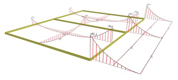
In the region of the continuity with the cantilever support moments are -30.6 kNm equal to almost isostatic moment of the cantilever. The higher moments of the cantilever - 41.0 kNm are the local peak moments, as shown in the next figure in the detailed distribution of the Mdue to the fixed transverse supports.


The 3D distribution of bending moments [Mx]

The positive peak moments forming a sharp “hole”, at the region of the support exactly behind the cantilever, results from the negative load created at this region by the cantilever’s moment.

Notice that the influence of the strong cantilever, both in negative and positive moments, decreases in a small distance from the cantilever support.

The insignificant differences in values of moments Mx between ‘FEM results’ and ‘Slab results’ are due to the relatively small curvature of the 3D moment diagram

Mx

.

Distribution of bending moments [My] extend only in the regions of top supports

Negative moments are developed on most of the region of the two-way slabs due to the strong cantilever support.

Along most of the support of the cantilever and the two-way slabs, bending moments have a value of-31.1 kNm whereas near the supports peak values occur within a width less than 1.0 m.


Deflections from ‘Slabs Results’

The maximum elastic deflection along the cantilever free edge varies from -2.75 mm at the mid-dle to -2.81 mm at both ends. The maximum deflections on the center spans are -0.64 mm.