en-USel-GRes-ES
Menu

Carpenter’s drawings II (es-ES)

The structural frame
The construction (es-ES)
The reinforcement I (es-ES)
The reinforcement II (es-ES)
Quantity/Cost estimation (es-ES)
Detailing drawings (es-ES)
Tomo A´ - Introducción

Materials (es-ES)
To be continued > (es-ES)
Tomo C´ - Introducción

3D excavation drawing

The coordinates x, y, z in the coordinates system of the works are marked at every corner of the excavation’s peripheral polygon. In this specific example, the origin of the coordinates system (x,y) has been defined as the lower left edge of the building plot and the origin of the z axis as the middle of the forefront’s side walk which coincides with the 0.0 as set in the urban planning drawing.

Concreting phase of basement floor

>

The concrete class of the basement floor must be the same as the one used for the structural frame because it also covers the columns and shear walls layer.

Detail of drawing C.30

>

The detail of the waterproofing of the two joints formed at the base of the perimeter shear walls where the layers of three concrete castings meet is quite important. When it is possible to work at the outer surfaces, the solution is shown at the figure.

Detail of the central staircase, of drawing C.50

>

Detail for the design of the balcony arc in drawing C.50

>

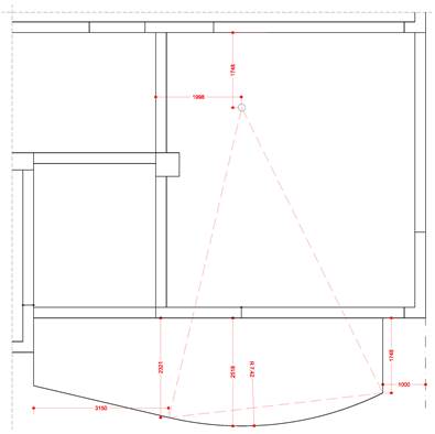
When the formwork includes curved sections, the information required for their design must be provided. For instance, in the case of a circle’s arc, the center of the circle, its radius and two points on its circumference can be indicated.
For an effortless and accurate implementation of the curved side of the slab’s formwork, when the circle’s radius is known, small wooden, plastic or steel models can be created in natural size with a length around e.g. 50 cm, which can be used as drivers for the support of the flexible side mould.