en-USel-GRes-ES
Menu

Appendix D (es-ES)

The structural frame
The construction (es-ES)
The reinforcement I (es-ES)
The reinforcement II (es-ES)
Quantity/Cost estimation (es-ES)
Detailing drawings (es-ES)
Tomo A´ - Introducción

Materials (es-ES)
To be continued > (es-ES)
Tomo C´ - Introducción

Subject description

GThe structural frame with 6 levels, project <B_d1>

In appendix Β’, the crossbar was used to assess the behaviour of the multistorey plane frame.
In this chapter, the composition of space frames, through beams and slabs, is considered. The diaphragm is the structural unit for the assessment of coupled space frames.

The space frame structural model with bars of columns and beams and diaphragms

A diaphragm is the horizontal part of the floor consisting of slabs, connecting beams and columns. A floor may comprise more than one diaphragm, as shown in the example building of the present paragraph.


The most characteristic point of the diaphragm is the centre of stiffness.


The centre of stiffness CT of a specific floor diaphragm is defined as the point about which the diaphragm rotates, under horizontal seismic force H.

The CT point depends only on the geometry of the floor and is independent of the loadings, meaning that regardless the magnitude of the force, which may become equal to 2H, or 3H, or any other value, the centre of stiffness will remain the same. Of course, it depends on the geometry of the overlying and the underlying floors.


Principal axis system of diaphragm

is defined as the orthogonal axis system xCTy, in which when a horizontal seismic force H is applied on CT, along axis x (or y), it results in translating CT only along axis x (or y respectively). The angle of the principal system, as to the initial system X0Y, is called principal angle of the diaphragm.


Floor plan of 5th level and diaphragm on the left examined next
(The cross-sections of columns, walls and beams are 500/500, 2000/300 and 300/500 respectively)

The above diaphragm data as well as the torsional stiffness Kθ and torsional ellipse stiffness ellipse (CT, rx, ry), should be calculated in a general way. The method to be used should deal with more than one diaphragm per floor. Moreover, the general solution should account for the influence of non-diaphragmatic frames as well as the uneven level foundation. All possible special cases met in practice are included in the example presented in this paragraph, except for foundations, just for simplification reasons. Full scale analysis (including the foundation), can be performed by the engineer using the related software.

The behaviour of diaphragm on the left at the 5th level, analysed next is directly affected by the L-type frame C21-C26-C27-C28 connected to it and indirectly by column C6 and the diaphragm on the right, through the frames of other floors.

A general method for the calculation of the diaphragm data is presented next.

This method creates a condition allowing the diaphragm only to rotate about the centre of stiffness CT, which remains stationary with respect to the ground.

The method comprises four steps, the first three of which include a space frame analysis.


General method for the calculation of the diaphragm i data
Step 1: Analysis under force HΧ and concentrated moment MCM,X applied at the centre of mass of diaphragm i

Loading: Force HX=100 and moment MCM,X on centre of mass CM of diaphragm i
Results: total displacements of structure and displacements of diaphragm i

The two displacements δXX1, δXY1 of point 1 of diaphragm i and its angle θXZ are required.

Any value may be given to force HΧ, as long as it is the same for the analyses of the three first steps. In this example, HΧ is given equal to 100 kN. The application point of force H is irrelevant, but for higher accuracy in calculations, the force is assumed applied at an arbitrary eccentricity cy, e.g. 2.0 m, in relation to the centre of mass, in order to produce a significant rotation of the diaphragm and thus achieve a higher accuracy in the calculations. That eccentricity is essential, especially in cases where the centre of stiffness is close or coincides with the centre of mass. Therefore, in addition to force HΧ, moment MCM,x=100kN×2.00m= 200 kNm is also applied at CM.

The diaphragm displacements in plan, due to 2 parallel translations δXXo, δXYo and one rotation θXZ

Point 1 corresponds to column Κ2 joint, but could be any point of the diaphragm.

The only results needed from this analysis are the translations of point 1 δXX1=2.681 mm, δXY1=-0.231 mm and the angle θXZ=4.5613×10⁻⁵ of the diaphragm. The displacements of point 2 will be used only to verify the generality of the method.

All displacements are absolute with respect to the ground.


Step 2: Analysis under force HΧ applied at the centre of mass of dia-phragm i with rotational restraint

Loading: HX=100 on diaphragm i with rotational restraint

Results: the total displacements of structure and the two parallel translations of diaphragm


The two translations of point 1 δXXo, δXYo, are only required, being identical for any point of the diaphragm i, thus also for CT, since the angle of rotation of the diaphragm is zero.

The 2 parallel translations of the diaphragm δXXo, δXYo, in plan

All diaphragm points, thus also CT, have identical displacements

Diaphragm is restrained against rotation, therefore θXZ=0

Due to zero rotation of diaphragm i, point 1 has only two parallel translations, δXXo=2.103 mm and δXYo=-0.047mm, being identical for all diaphragm points, thus also for CT. In other diaphragms located in the same, upper or lower level, small, yet measurable rotations exist, thus every point on them has different displacements.


Step 3: Analysis under force HΥ applied at the centre of mass of dia-phragm i with rotational restraint

Loading: HY=100 on diaphragm i with rotational restraint
Results: the total displacements of structure and the two parallel translations of diaphragm

The two translations of point 1 δXXo, δXYo, are only required, being identical for any point of the diaphragm i, thus also for CT, provided that the angle of rotation of the diaphragm is zero.


The 2 parallel diaphragm translations δXXo, δXYo, in plan


All diaphragm points, thus also CT, have identical displacements

Diaphragm is restrained against rotation, therefore θXZ=0

Due to zero rotation of diaphragm i, point 1 has only two parallel translations, δYXo=-0.047 and δYYo=1.668 mm, being identical for all diaphragm points, thus also for CT. As in step 2, in other diaphragms located in the same, upper or lower level small, yet measurable rotations exist, thus every point on them has different displacements.

The secondary displacements δXYo of loading 1 and δYXo of loading 3 are always equal, i.e.  δXYo=δYXo should always derive from the space frame analysis.

Analysis 3 is performed only to obtain translation δYYo needed for the calculation of angle a of the principal system.

The angle a of the principal system of diaphragm i is calculated by means of the equation C.9.1 of §C.9 using the 2nd and 3rd analysis results:

tan(2a)=2δXYo/(δXXo-δYYo)=2×(-0.047)/(2.103-1.668)=-0216 2a=-12.2º → a=-6.1º


Step 4: Analysis results from loading 1 minus analysis results from loading 2, meaning that only moment and only rotation exists about the centre of stiffness CT, which remains stationary with respect to the ground

The only load acting on diaphragm i is moment on CT

Diaphragm displacements are induced only due to rotation

The centre of stiffness CT remains stationary with respect to the ground


Using this trick, namely by subtracting analysis 2 results from analysis 1 results, the diaphragm i develops only rotation, while the remaining diaphragms develop both translations and rotation. However only diaphragm i is examined here. The most important result of this trick is that the diaphragm i is rotated about CT, which remains stationary with respect to the ground, allowing the calculation of its precise location. The rotation angle of diaphragm i is the rotation angle θXZ calculated in step 1 under the corresponding loading.

Determination of center of elasticity

The displacements of an arbitrary point j of the diaphragm, due to rotation θXZ derive form the expressions:

δΧtj=δXXj-δXXo, δYtj=δXYj-δXYo

The CT coordinates corresponding to these displacements are:

XCT=Xj-δYtj/θXZ

YCT=Yj+δXtj/θXZ

In the example considered, for point 1:

δΧt1=δXX1-δXXo=2.681-2.103=0.578 mm

δYt1=δXY1-δXYo=-0.211-(-0.047)=-0.164 mm

The diaphragm rotation is identical to that of analysis 1, i.e. θXZ=4.5613·10-5.

The coordinates of point 1 are (6.0, 0.0), thus:

XCT=X1-δYt1/θXZ=6.0-(-0.164)·10-3/(4.5613·10-5)=9.6 m

YCT=Y1+δXt1/θXZ=0.0+0.578·10-3/(4.5613·10-5)=12.7 m


Diaphragm lateral stiffnesses

Each diaphragm has two lateral stiffnesses in the two principal directions.

Lateral stiffness of diaphragm Kxx (or Kyy) along the principal x (or y) direction, is defined as the ratio of the seismic force H to the corresponding δxo (or δyo) displacement of the diaphragm, when force acts on CT along the principal direction considered, i.e.:

Kxx=Hxx/δxxo , Kyy=Hxy/δxyo or equivalent:  Kxx=Hyx/δyxo , Kyy=Hyy/δyyo

Using analysis 2, the external force HX=100 of the initial system X0Y is resolved into two equivalent principal forces Hxx=100·cosa and Hxy=-100·sina (see §C.2) acting in x,y directions of the principal system. In the present case, a=-6.154º, therefore Hxx=100·0.994=99.4 kN and Hxy=-100·(-0.107)=10.7 kN.

Respectively, the two translations of the centre of stiffness in X0Y, derived from analysis 2, are δXXo=2.103, δΧΥο=-0.047, which transferred in the principal system yield (§C.2):

δxxo=δXXo·cosa-δXYo·sina=2.103·0.994-(-0.047)·(-0.107)=2.090-0.005=2.085 mm

δxyo=-δXXo·sina+δXYo·cosa=-2.103·(-0.107)+(-0.047)·0.994=0.225-0.047=0.178 mm

Kxx=Hxx/δxxo=99.4·103N/2.085·10-3m=47.7·106 N/m

Kyy=Hxy/δxyo=10.7·103N/0.178·10-3m=60.1·106 N/m

Diaphragm torsional stiffness

Torsional stiffness of diaphragm Kθ is defined as the ratio of moment MCT acting on the centre of stiffness CT, to the rotation angle θz of the diaphragm.

Moment acting on CT is equal to

MXCT=100.0·(YCT-YCM)+100.0·cY=100·(12.685-12.323)+200.0=36.2+200.0=236.2 kNm

Kθ=MXCT/θXZ=236.2·103Nm/4.5613·10-5=5178·10Nm

Torsional stiffness distribution

Torsional stiffness distribution of diaphragm is the curve on which, if the idealised columns with the same lateral stiffnesses as those of the diaphragm, are placed symmetrically with respect of the centre of stiffness, the torsional stiffness derived is the same as that of the diaphragm.

Torsional stiffness ellipse of diaphragm is defined as the ellipse having CT as centre and rx=√(Kθ/Kyy), ry=√(Kθ/Kxx) as radii.

rx=√Kθ/Kyy=√[5178×106Νm/60.1×106N/m]=9.28 m
ry=√K
θ/Kxx=√[5178×106Nm/47.7×106N/m]=10.42 m


Equivalent system – Relative lateral stiffness – Relative torsional stiffness

The equivalent building should comprise same number of floors and diaphragms. The columns of each floor should have specific dimensions, thus for each floor relative lateral and torsional stiffnesses are used.

Each diaphragm is replaced by an equivalent one consisting of 4 fixed-ended columns placed symmetrically with respect to its centre of stiffness.

The equivalent diaphragm i is assumed to behave as an one-storey structure of fixed-ended columns. The four relative translations of the centre of stiffness along X, Y axes δXXoΖ,i, δXYoΖ,i , δYXoΖ,i, δYYoΖ,i  as well as the rotation angle θXZMZ,I are defined as functions of the actual building displacements as follow.

δXXoΖ,i= δXXo,i-δXXo,i-1 , δXYoΖ,i=δXYo,i-δXYo,i-1 ,
δYXoΖ,i= δYXo,i-δYXo,i-1δYYoΖ,i=δYYo,i-δYYo,i-1,
θXZΜZ,i = θXΖΜ,iθXZΜ,i-1.

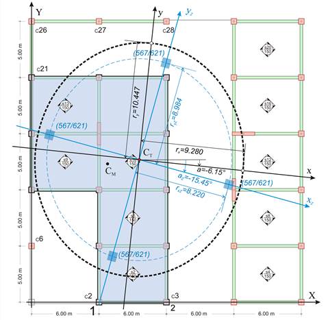
Therefore, the data of the equivalent diaphragm are: rotation angle az,i=2δXYoΖ,i/( δXXoΖ,i- δYYoΖ,i),

torsional stiffness KθZ,i=H·cY/ θXZΜZ,i , lateral stiffnesses KxxZ,i= H/(δXXoZ,iXYoZ,i·tanaZ,i) και KyyΖ,ι=H/(δYYoZ,iXYoZ,i·tanaZ,i) (equations C.9.2 and C.9.3 of §C.9).

Also rxZ,i=√KθZ,i/KyyZ,i, ryZ,i=√KθZ,i/KxxZ,i

The location of the equivalent diaphragms is determined by translating the centre of stiffness to point 0.0, 0.0. In this way the equivalent building is created and for its diaphragms i the following relations apply:

δXXo_equal,i=Σ(δXXoΖ,k) όπου k=i έως 1 à δXXo_equal,i=Σ(δXXo,i-δXXo,i-1)= (δXXo,i-δXXo,i-1)+ (δXXo,i-1-δXXo,i-2)+…+ (δXXo,1-0.0)=δXXo,i à δXXo_equal,i=δXXo,i

Using the same logic δXYo_equal,i=δXYo,i , δYYo_equal,i=δYYo,i και  θXZ_equal,i= θXZΜ,i

Therefore all diaphragm quantities Kxx_equal,i , Kyy_equal,i , Kθ_equal,i are equal to those of the actual building.

The seismic assessment of the actual building can be performed in an easy, direct and descriptive way by means of the equivalent building.