en-USes-ES
Menu

Multistorey plane frames (es-ES)

Multistorey plane frame systems

Four-storey frame type structure comprising three columns (project <B_531>)

Stiffnesses K and stiffness factors k of the columns composing the one-storey frames of the previous paragraphs, reflect the actual ones, as depending only on the geometry and not on the magnitude of the forces or their distribution along the height of the building,  since the structures were only single storey. These stiffnesses were the absolute ones, but at the same time they were also the relative ones as there was only one storey.

In multistorey buildings, considered in this paragraph, the seismic forces are applied along the structure height and therefore another factor is involved, namely the distribution of horizontal seismic forces (orthogonal, triangular and random). Consequently, stiffnesses are independent of the force magnitude, but dependent on the horizontal seismic force distribution. Eventually, both stiffnesses K and stiffness factors k derived will be the apparent values.

Assuming that the horizontal forces act simultaneously at the floors, the apparent floor stiffness is meant to be relative with respect to its lower one.


Column frame type structure with triangular distribution of seismic forces
(practical graphical representation)

project <B_531>

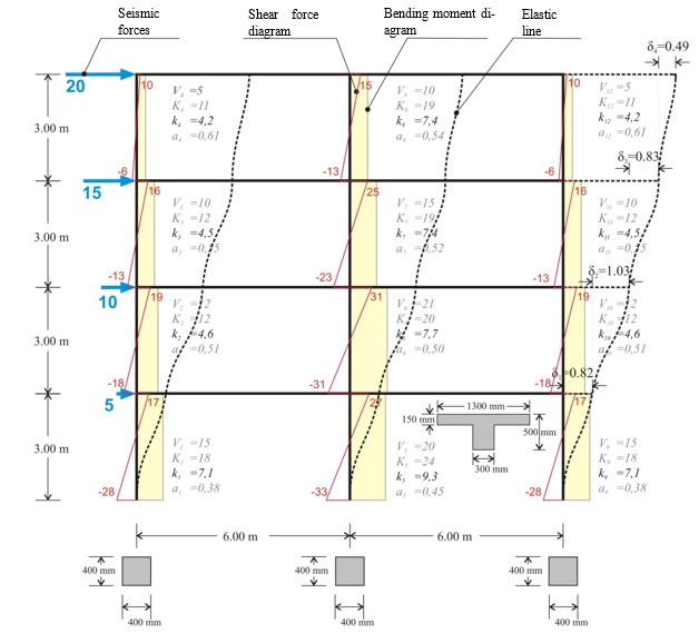
The following project <B_531> of a multistorey plane frame shows the interstorey fluctuation of the apparent stiffness factor kj and the moment distribution factor aj in both middle and end columns.

The apparent stiffness factors kj vary from 4 to 9, while the moment distribution factors aj from 0.40 to 0.60.

The apparent stiffnesses are independent of the seismic force magnitude. They depend only on the distribution of forces along the height of the frame. To this end, in the following examples, both forces, shear forces, bending moments, and deformations are unitless.

The characteristic value of the seismic action is the total horizontal force, henceforth called “base shear” because it is equal to the sum of all column shear forces at the base of the building. In the specific example, where the triangular distribution is used, the base shear is equal to 50. If equal horizontal forces Vbase=50 are applied by means of orthogonal distribution, i.e. horizontal force H=12.5 at each floor, the results differ by a small percentage of the order of 5%.

In case of a basement, seismic forces developed at its roof level have a zero value. However, fixed end condition applies only to the base of the columns along the basement perimeter walls.

If the frame also comprises walls, as presented in the following paragraph, the stiffnesses and the moment distribution of the walls differ between them. This difference becomes more distinctive as the number of stories increase.

The total joint displacements and column stress resultants (shear forces and bending moments) are obtained from the frame analysis. Quantities K, k and a derive from the previous results. The apparent stiffness Ki of storey i derives from the expression Ki=Vi/δi, while the apparent stiffness of column j of storey i from the expression Ki,j=Vi,j/δi.

Example (3rd storey):

Column stiffnesses: K3,1=9.6/0.823=12, K3,2=15.8/0.823=19, K3,3=9.6/0.823=12.

Storey stiffness: Κ3= (20+15)/0.823=43. The same value is obtained if calculated as the summation of the column stiffnesses of the storey, i.e.  K3= K3,1+K3,2+ K3,3=43.

If shear effect is taken into account (Shear effect=ON), the displacements are δ1=0.85, δ2=1.05, δ3=0.84, δ4=0.50 mm, i.e. the difference is insignificant.

If rigid bodies effect is taken into account (Rigid body=ON), the displacements are δ1=0.80, δ2=0.97, δ3=0.77, δ4=0.45 mm, i.e. both decrease of displacements and increase of stiffnesses are small but measurable.


Multistorey plane dual systems

Four-storey dual type structure comprising two columns and a wall (project <B_532>)

If the frame also comprises walls, the differences in stiffnesses and in moment distributions be-come more intense as the number of stories increase.

Multistorey dual type structure with triangular distribution of seismic forces
( “hand-made” graphical representation)


In the multistorey plane frame of project <B_532> the interstorey fluctuation of the apparent stiffness factors kj and the moment distribution factor aj in both columns and wall is presented.

Example (3rd storey):

Column stiffnesses: K3,1=4.6/0.329=14, K3,2=25.9/0.329=79 K3,3=4.6/0.329=14.

Storey stiffness: Κ3= (20+15)/0.329=107. The apparent relative stiffness of the storey can also derive from the sum of its column stiffnesses, i.e. K3= K3,1+K3,2+ K3,3=107.

If shear effect is taken into account (Shear effect=ON), the displacements are δ1=0.14, δ2=0.30, δ3=0.34, δ4=0.32 mm, i.e. the difference is small.

If, however, rigid bodies effect is taken into account (Rigid body=ON), the displacements obtained are significantly smaller equal to δ1=0.12, δ2=0.22, δ3=0.24, δ4=0.21 mm, leading to much larger stiffness values.

In case of a basement, zero seismic forces are developed at its roof level. However the fixed end condition applies at the bases only of the columns located at the basement perimeter walls.

In the multistorey dual frame, the column factors are characterized by relatively small fluctuations with k  varying from to and from 0.35 to 0.55.

On the contrary the corresponding fluctuation in the wall factors is significant with varying from 0.10 to 1.50 and from 1.0 to -1.0


Comparison of multistorey frame and dual systems

The behaviour of the most common structural systems will be now examined. The structural system comprising only columns is called a frame system, while the one comprising both columns and walls is called a dual system.


The comparison of the two systems will be performed by means of examples. The structures under consideration are those used in the two previous paragraphs while the corresponding number of storeys is 4, 8 and 15. Two main quantities are compared, an actual one and an idealised one. The displacement of each level is the actual quantity and the equivalent column cross-section of each storey is the idealised one. The term equivalent column defines a theoretical column which develops a displacement equal to that developed by all storey columns. Infinite types of such idealised equivalent columns could be considered, however the fixed-ended one with 300 mm width is selected here. Alternatively, the rectangular fixed-ended column could be considered as equivalent.

In the comparison of the two systems, the distribution and not the magnitude of the seismic forces plays an important role. Consequently, the triangular distribution is used, approximating to the extent possible the actual distribution of the majority of buildings designed by an engineer. In the related software the seismic forces are imposed on the considered building by selecting Apply Seismic Forces=ON in the dialog located in the central menu: “Horizontal Forces” à “Seismic Forces”.

The three examples under consideration in both frame and dual versions are included in the related software. The modelling accounts for the elastic stiffnesses (Beam & Column Inertia Factor=1), the rigid bodies effect (Rigid Body=1) and the shear effect (Shear Effect=1). 


Four-storey structures (frame and dual type) under the same seismic loading (a)

FRAME type structure comprising three columns with cross-section 400/400
and Equivalent structure of one fixed-ended column per storey

The interstorey stiffness variation of the frame type structure is small (equivalent cross-section 570/300 at level 1 and 505/300 at level 4).


Four-storey structures (frame and dual type) under the same seismic loading (b)

DUAL type structure  comprising one wall with a cross-section of 2000/300
  and two columns a with a cross-section of 400/400
and Equivalent structure of  one fixed-ended column per storey

The interstorey stiffness variation of the dual type structure is significant (equivalent cross-section 1170/300 at level 1 and 660/300 at level 4).


Eight-storey frame type structure under triangular seismic loading

    Notes:

  • · In both frame and dual systems, for each column Mo-Mu=V×h, where Mo is the moment at the top, Mu is the moment at the base, V is the shear force and h is the height of the column. For instance, for the middle column of the previous structure 98.7-(-115.6)=71.4×3.0 (214.3≈214.2).

  • · In all types of structures, frame or dual, the sum of column shear forces of a storey is equal to the sum of the seismic forces of all the above storeys. Indicatively, for the first storey the sum is 54.3+71.4+54.3=180, while for the last 10.7+18.6+10.7=40. The middle column of the first storey carries the 71.4/180=40% of the total shear force, while each of the end columns carries 30%. In the last storey the middle column carries the 18.6/40=46%, while each of the end columns carries 27%.

Eight-storey dual type structure under triangular seismic loading

Notes:

·         In the first storey, the sum is 10.6+158.9+10.6=180. The wall carries 158.9/180=88% of the total shear force, while each column carries 11%. In the last storey, the sum is 13.8+12.5+13.8=40. The wall carries 12.5/40=32% of the total shear force, while each column 34%. It is concluded that the wall has a favourable effect on the first storey columns, in contrast to that corresponding to the last storey.

·         The expression Mo-Mu=V×h, applies for both columns and wall. Indicatively, for the first storey wall -309.9–(-786.4)=158.9×3.0 (476.5≈476.7), while for that of the last storey 89.8-52.3=12.5×3.0 (37.5=37.5).The maximum displacement of the dual type structure is equal to 8.08 mm, i.e. almost three times smaller than the one corresponding to the frame type structure (22.51 mm).


Fifteen-storey frame type structure under triangular seismic loading

The maximum displacement of the frame type structure is equal to 160 mm, i.e. almost twice of that corresponding to the dual type structure (75 mm).

Fifteen-storey dual type structure under triangular seismic loading

It should be emphasised that in all previous examples, the comparison of the two structural sys-tems is important rather than the absolute quantities, which after all derive from specific values of the seismic forces. These values have been selected arbitrarily, yet satisfying the triangular distribution rule.

Comparative table of Frame and Dual structural systems


Effects

Structural System

Practical conclusions

Frame

Dual

Displacements magnitude

large

small

Need for wide seismic joint between buildings in frame systems.

Earthquake resistance of brick walls

small

large

EC8 prohibits in general using brittle walls e.g. brick walls for High Ductility Class (DCH) (see §6.1.5.4).

Fluctuation of interstorey relative displacements and stiffnesses

small

large

In dual systems, walls develop a favourable behaviour in lower while frames develop a favourable behaviour in upper storeys. To this end, the coexistence of both frames and walls in a structure is necessary (dual system).

Foundation effect

small

large

Walls should be founded on foundation beams of high stiffness. The more efficient foundation for walls way is on the basement walls ensuring fixity at their base.

Shear effect

small

significant

The shear effect should be taken into account in the design of dual systems in contrast to the design of frame systems where it can be omitted.

Rigid bodies effect

small

significant

The rigid bodies effect should be taken into account in the design of dual systems while in the design of frame systems it can be omitted.

The behaviour of dual systems is more favourable than
frame systems under seismic actions.