en-USel-GRes-ES
Menu

Exercises (es-ES)

Exersise 4.9.1 (project <B_49-1>)

 The design combination in ultimate limit state (ULS) is obtained by load p=γg×g+γq×q equal to:


p=1.35g+1.50q=1.35×5.25+1.50×5.00=14.59 kN/m2


Three different methods for the calculation of the two-way slab, by means of Marcus, Czerny and finite element method are presented below.

Given: Covering load ge=1.00 kN/m2, live load q=5.00 kN/m2,

concrete quality C30/37 (E=32.8 GPa).

Question: Perform static analysis to determine bending moments, shear forces, support reaction forces and elastic deflection

Solution:

Finite element method: Results summary

Mx=12.9 kNm, My=7.6 kNm          Vx=22.1 kN, Vy=20.1 kN                           y=-1.73 mm

Finite element method: Analytical results

Bending moment distribution M11          Shear force distribution V11                       Deflections

Exersise 4.9.2 (project <B_49-2>)

Given: Covering load ge=1.5 kN/m2, live load q=2.0 kN/m2, concrete quality C40/50 (E=35.2 GPa).

Question: Perform static analysis to calculate bending moments, shear forces, reaction forces, deflections and equivalent uniform loadings of slabs transferred onto beams.


Solution:

Self-weight

go=0.15m×25.0kN/m3=

3.75 kN/m2

Covering load

ge=

1.50 kN/m2

Total dead load

g1=g2=

5.25 kN/m2

Total live load

q1=q2=

2.00 kN/m2

Design load

p1=p2g×5.25+γq×2.0=

=1.35×5.25+1.50×2.0=


10.09 kN/m2


Finite element method: Results summary

Bending moment diagram

Finite element method: Results summary

Shear forces diagram

Finite element method: Results summary

Deflections

Finite element method: Analytical results

Bending moment distribution M11

Finite element method: Analytical results

Shear force distribution V11

Finite element method: Analytical results

Deflections


Exersise 4.9.3 (project <Β_49-3>)

Given: Covering load ge=1.00 kN/m2, live loads of domestic use q1=q2=2.00 kN/m2, q3=5.00 kN/m2, concentrated load applied at the free end of the cantilever G3=1.00 kN/m.

Question: Perform static analysis for the slabs illustrated in the figure (a) under global loading and (b) taking into account the effect of live loads.


Solution:

In ULS, the minimum design load for each slab is equal to gd,i=1.00·g, whereas the total design load is equal to pd,ig·giq·qi. In this case gd,i=1.00·5.00=5.0 kN/m and Gd,3=1.00·1.0 kN (concentrated load). The maximum design load for the first two slabs is equal to pd,1=pd,2=1.35·5.00+1.50·2.00=9.75 kN/m, while for the third’s slab  (balcony) is equal to pd,3=1.35·5.00+1.50·5.00=14.25 kN/m και Pd,3=1.35·1.00=1.35 kN.


(Α) Global loading

ULS design load is applied simultaneously on each slab.

(Β) Unfavourable loadings


For this particular structure, the following six unfavourable loadings cases are required.

For each loading case the expressions giving the solution are identical:

M10=-p1·l012/8, M2=-p3·l232/2-P3·l23, M12=-p2·l122/8-M2/2, M1=(M10+M12)/2,
V01=p1
·l01/2+M1/l01, V10=-p1·l01/2+M1/l01 , V12=p2·l12/2+(M2-M1)/l12, V21=-p2·l12/2+(M2-M1)/l12

V23=p3·l23+P3, V32=P3

maxM01=V012/(2·p1), maxM12=V122/(2·p2)+M1maxM01=V012/(2·p1),  maxM12=V122/(2·p2)+M1


GLOBAL LOADING ANALYSIS

UNFAVOURABLE LOADINGS ANALYSIS
1st loading case: maxΜ01, minM1

UNFAVOURABLE LOADINGS ANALYSIS
2nd loading case: minM01, maxM12

UNFAVOURABLE LOADINGS ANALYSIS
3rd loading case: minM1

UNFAVOURABLE LOADINGS ANALYSIS
4th loading case: minM2

UNFAVOURABLE LOADINGS ANALYSIS
5th loading case: maxΜ1

UNFAVOURABLE LOADINGS ANALYSIS
6th loading case: maxM2

ENVELOPE DIAGRAMS

The global loading diagram is illustrated with dashed line pd=1.35×g+1.50×q

Global loading, Shear force diagram (related software)

Global loading, Bending moment diagram (related software)

Unfavourable loadings, Shear force envelope (related software)

Unfavourable loadings, Bending moment envelope (related software)

Exersise 4.9.5 (project <B_464>)

Given: Covering load gεπ=1.5 kN/m2, live load q=5.0 kN/m2, concrete quality C40/50.

Question

: Perform static analysis of the slabs illustrated in the figure (shears forces, bending moments, deflections) using the finite element method with (a) global loading and (b) unfavourable loadings.


RESULTS FOR GLOBAL LOADING 1.35g+1.50q

Bending moment diagram

Mx=13.9 kNm, My=12.4 kNm, Myerm=-34.6 kNm


RESULTS FOR GLOBAL LOADING 1.35g+1.50q

Shear force diagram

Vxr=23.6 kN, Vyr=24.1 kN, Vyerm=45.5 kN


RESULTS FOR GLOBAL LOADING 1.35g+1.50q

Deflection diagram

ymax=4.03 mm


RESULTS FOR GLOBAL LOADING 1.35g+1.50

Deflection diagrams and contours

RESULTS FOR UNFAVOURABLE LOADINGS

Bending moment diagrams

Mx=15.5 kNm, My=12.4 kNm, Myerm=-34.6 kNm


RESULTS FOR UNFAVOURABLE LOADINGS

Shear force diagrams
Vxr=24.8 kN, Vyr=24.5 kN, Vyerm=45.5 kN

RESULTS FOR UNFAVOURABLE LOADINGS

Deflection diagrams

ymax=4.39 mm


RESULTS FOR UNFAVOURABLE LOADINGS

Deflection diagrams and contours

Exersise 4.9.7

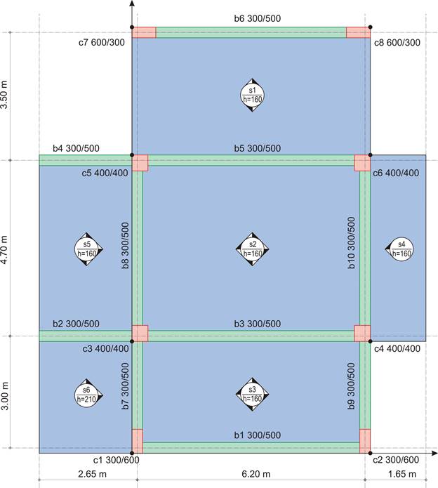
Given: Thickness of slabs s1, s2, s3, s4, s5: h=160 mm, s6: h=210 mm and covering load gεπ=2.0 kN/m2.

Question: Perform static analysis to determine the distribution of slabs loads transferred onto beams

Static analysis

g1,2,3,4,5=0.16·1.0x25.0=4.0 kN/m2, g6=0.21·1.0x25.0=5.25 kN/m2, gεπ=2.0 kN/m2

Analysis will be performed using the global load (due to the small value of the live load):

p1,2,3,4,5=6.0·1.35+2.0·1.5=11.1 kN/m2, p6=7.25·1.35+2.0·1.5=12.80 kN/m2

Thus, on 1.0 m wide strips, the respective loads are p1, 2,3,4,5=11.1 kN/m and p6=12.80 kN/m

επομένως, σε ζώνη πλάτους 1.0 m, αντιστοιχεί φορτίοp1,2,3,4,5=11.1 kN/m και p6=12.80 kN/m.


Final stress resultants

In general, the most unfavourable span moments, arise in one-way slabs (s1) or cantilever slabs (s4) at one point in the first direction and at one line in the other. In two-way slabs moments are developed at the same point in both directions.

Slabs load distribution


Bending moment distribution, produced by the related software