|
|
|
|
|
Figure 6.5-3
B: +1.00EX + 0.30EY
|
Figure 6.5-4
C: +1.00EX - 0.30EY
|
Figure 6.5-5
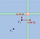
D: +0.30EX + 1.00EY
|
Figure 6.5-6
E: -0.30EX + 1.00EY
|
|
|
|
|
|
|
Figure 6.5-7
F: -1.00EX - 0.30EY
|
Figure 6.5-8
G: -1.00EX + 0.30EY
|
Figure 6.5-9
H: -0.30EX – 1.00EY
|
Figure 6.5-10
I: +0.30EX – 1.00EY
|
Regardless of the CM, CT locations the combination A of gravity loads g and q multiplied by the safety factors of actions always exists . For any specific location of CM, CT, 8 additional combinations of the seismic forces exist, due to the most probable masses 1.00g+0.30q during the earthquake.